-
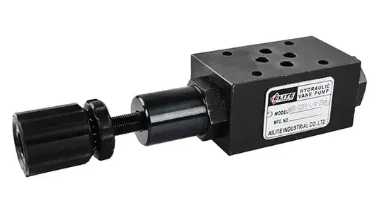
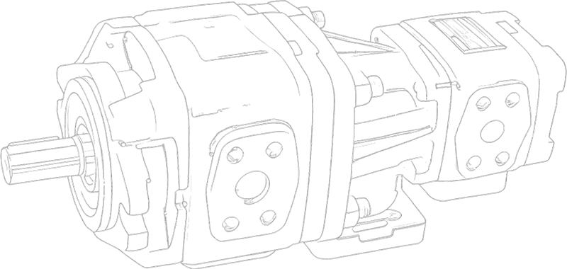
The hydraulic stack valve utilizes a modular design to integrate multiple functions such as directional control, pressure control, and flow control. This reduces piping connections and simplifies system design.
| Model | Max. operating pressure (MPa) | Max. flow (L/min) |
|
|
21 | 35 |
|
|
31.5 | 70 |
| Model | Max. operating pressure (MPa) | Max. flow (L/min) |
|
|
31.5 | 35* |
|
|
25 | 70* |
| Model | Max. operating pressure (MPa) | Max. flow (L/min) |
|
|
14.0 | 20* |
|
|
14.0 | 40* |
| Model | Max. operating pressure (MPa) | Max. flow (L/min) | Free flow |
|
|
25.0 | 35 | — |
|
|
25.0 | 35 | 35 |
| Model | Max. operating pressure (MPa) | Max. flow (L/min) |
|
|
31.5 | 35* |
|
|
25 | 70* |
| Model | Max. operating pressure (MPa) | Max. flow (L/min) |
|
|
31.5 | 60 |
|
|
25 | 120 |
| Model | Max. operating pressure (MPa) | Max. flow (L/min) |
|
|
25 | 70 |
|
|
25 | 70 |
|
|
25 | 70 |
|
|
25 | 70 |
|
|
25 | 70 |
External piping between components, such as hoses, tubes, and fittings, is unnecessary. This avoids potential leaks that can occur with external piping.
Under clean conditions, fully screw four double-ended studs into the threaded holes on the designated base plate, subplate, or integrated block mounting surface. Stack the stacking valves and solenoid directional valves according to the hydraulic circuit, placing the side with the O-ring on the base plate. Ensure correct positioning before stacking valves using the double-ended studs. Align the ends of the stacked valves. Screw the four nuts onto the double-ended studs and tighten them to the specified torque. After trial operation, be sure to re-tighten the nuts securely within the specified torque range.
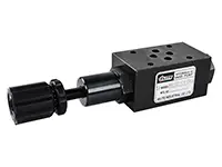
To adjust the pressure, loosen the lock nut, then rotate the pressure adjustment screw clockwise or counter-clockwise. To increase the pressure, rotate the screw clockwise. After adjusting the pressure, always remember to re-tighten the lock nut.
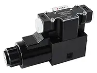
Explore NOAH’s DSG solenoid directional valves—durable, low-noise, ISO-compatible valves rigorously tested for over 10 million cycles.
The hydraulic stack valve utilizes a modular design to integrate multiple functions such as directional control, pressure control, and flow control.